Introduction
We just had a Jaycar open in our area and I’ve taken it upon myself to drop in and pick up some in-expensive components every now and then in preparation for some of the Arduino/Pi based units I’ll be taking next semester when Uni goes back.
I was able to pick up a relatively cheap analog thumbstick today and I came up with the idea to have it control one of the RGB LED units I had sitting around gathering dust at home. I didn’t want to over complicate the project, as I didn’t have a huge amount of experience with the platform and was honestly going to be happy just getting analog serial readings from the thumbstick showing in the Arduino IDE.
Part List
The following parts were used throughout the build of this project:
1x Arduino UNO
1x Analog Thumbstick
1x RGB LED Module
3x 220Ω Resistor
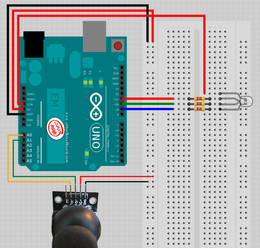
10x Jumper wiresThe final schematic I’ll be referring to throughout the design process is shown below. Output pins on the Thumbstick module might vary on different units, so just make sure your unit lines up with the four important pins I’ve used in my build.
Reading input from the Thumbstick
To start with I wanted to make sure that I could easily read from logical values from the thumbstick. In order to do this I connected the VRx and VRy lines to the Analog IN Pins AO and A1 on the Arduino board.
I then ran 5 volts and a grounding line to the other two pins on the thumbstick. The following code was then used to read from the Analog PINs and output the results to the Serial console.
// Analog PIN Declarations
const int sensorPinX = A0;
const int sensorPinY = A1;

void setup() {
  // open a serial port
  Serial.begin(9600);
}

void loop() {
  // Read sensor values
  int sensorXValue = analogRead(sensorPinX);
  int sensorYValue = analogRead(sensorPinY);

  // Print results to console
  Serial.print("X Axis Value: ");
  Serial.println(sensorXValue);
  Serial.print("Y Axis Value: ");
  Serial.println(sensorYValue);
}
Writing this code to the board and executing immediately gave me positive results spilling into the console.
X Axis Value: 1019
Y Axis Value: 500
X Axis Value: 1019
Y Axis Value: 500
X Axis Value: 1019
Y Axis Value: 252
X Axis Value: 1019
Y Axis Value: 39
X Axis Value: 1019
Y Axis Value: 0
X Axis Value: 1014
Y Axis Value: 0
X Axis Value: 811
Y Axis Value: 0
NOTE On some boards you might notice raw values similar to the following flow into the console
fž
fžffx˜˜æ˜à˜
˜€†f˜fž
fžffx˜˜æ˜à˜
˜€†f˜fž
fžffx˜˜æ˜à˜
˜€†f˜fž
fžffx˜˜æ˜à˜
˜€†f˜Fixing this problem is as simple as adding a delay to the bottom of the loop() function. It occurs because new values are fed into the microcontroller before it has time to write the values out the Serial lines.
// Delay allowing system to process
delay(30);
Understanding the RGB Module
The RGB unit I decided to use has four inputs. Three of those inputs take a variable voltage and uses that value to display a colour based on three sets of 0-255 integers (Red Blue Green combination).
First I added declarations for the high and low sensor values.
// Sensor High/Low Declarations
int sensorXLow = 0;
int sensorXHigh = 1023;
int sensorYLow = 0;
int sensorYHigh = 1023;
Then I setup a calibration test within my loop() that will update the sensor high and low values when they go above or below the expected results
// Calibrate High/Low X
if (sensorXValue > sensorXHigh){
  sensorXHigh = sensorXValue;
}
if (sensorXValue < sensorXLow){
  sensorXLow = sensorXValue;
}

// Calibrate High/Low Y
if (sensorYValue > sensorYHigh){
  sensorYHigh = sensorYValue;
}
if (sensorYValue < sensorYLow){
  sensorYLow = sensorYValue;
}
Using this setup means that I always deal with expected values and even if I do get a curve-ball input, my system will know how to deal with it.
Interface RGB Unit with PWM Pins
Now that we are importing logical data, we’re safe to move forward and interface the RGB unit. First I connected the Digital PWM pins in series with the RGB legs and a single 220Ω Resistor on each leg of my LED. Following that I added code to map the digital ports to meaningful names
// Digital/PMW PIN Declarations
const int redLEDPin = 11;
const int greenLEDPin = 10;
const int blueLEDPin = 9;
Next I setup RGB variable declarations and initialized them to 0;
// RGB Variable Declarations
int redValue = 0;
int greenValue = 0;
int blueValue = 0;
Within setup() I added code to initialize the three pinModes to OUTPUT
// set LED pins to output
pinMode(redLEDPin,OUTPUT);
pinMode(greenLEDPin,OUTPUT);
pinMode(blueLEDPin,OUTPUT);
Using the map() function in conjunction with the high and low X/Y sensor values; I scaled my raw inputs to values between 0-255. Because I didn’t have any good way of generating a value for the Blue pin input, I used a mix of the X and Y sensor values to generate a reasonable value for Blue.
// Calculate and map new values
int valueX = map(sensorXValue,sensorXLow,sensorXHigh, 0, 255);
int valueY = map(sensorYValue,sensorYLow,sensorYHigh, 0, 255);
int valueMix = map((sensorXValue+sensorYValue),0,1024, 0, 255);
Finally I added the following code to write the three final RGB values out to the LED
// Write values out to RGB LED
analogWrite(redLEDPin, valueX);
analogWrite(greenLEDPin, valueY);
analogWrite(blueLEDPin, valueMix);
Run the Code
Presto! my code works great
Below is a full copy of the final code used at runtime
// Analog PIN Declarations
const int sensorPinX = A0;
const int sensorPinY = A1;

// Digital/PMW PIN Declarations
const int redLEDPin = 11;
const int greenLEDPin = 10;
const int blueLEDPin = 9;

// RGB Variable Declarations
int redValue = 0;
int greenValue = 0;
int blueValue = 0;

// Sensor High/Low Declarations
int sensorXLow = 0;
int sensorXHigh = 1023;
int sensorYLow = 0;
int sensorYHigh = 1023;

void setup() {
  // open a serial port
  Serial.begin(9600);

  // set LED pins to output
  pinMode(redLEDPin,OUTPUT);
  pinMode(greenLEDPin,OUTPUT);
  pinMode(blueLEDPin,OUTPUT);
}

void loop() {
  // Read sensor values
  int sensorXValue = analogRead(sensorPinX);
  int sensorYValue = analogRead(sensorPinY);

  // Calibrate High/Low X
  if (sensorXValue > sensorXHigh){
    sensorXHigh = sensorXValue;
  }
  if (sensorXValue < sensorXLow){
    sensorXLow = sensorXValue;
  }

  // Calibrate High/Low Y
  if (sensorYValue > sensorYHigh){
    sensorYHigh = sensorYValue;
  }
  if (sensorYValue < sensorYLow){
    sensorYLow = sensorYValue;
  }

  // Calculate and map new values
  int valueX = map(sensorXValue,sensorXLow,sensorXHigh, 0, 255);
  int valueY = map(sensorYValue,sensorYLow,sensorYHigh, 0, 255);
  int valueMix = map((sensorXValue+sensorYValue),0,1024, 0, 255);

  // Print results to console
  Serial.print("X Axis Value: ");
  Serial.println(valueX);
  Serial.print("Y Axis Value: ");
  Serial.println(valueY);

  // Write values out to RGB LED
  analogWrite(redLEDPin, valueX);
  analogWrite(greenLEDPin, valueY);
  analogWrite(blueLEDPin, valueMix);

  // Delay allowing system to process
  delay(30);
}