Introduction
I’ve been putting off learning about interfacing for a while now. It isn’t because I don’t want to learn it though; In fact it’s probably the part of embedded systems that I was looking most forward to. No; the reason I’ve been putting it off is purely due to the difficulty I’ve had trying to find a good, concise explanation of how it all works. I’m not content just loading in the interfacing libraries and accepting that as complete; I would really like to understand what is actually happening on each pin that I’m interfacing with and maybe even understand what the driver is doing.
The Module
So lets get started! The module I purchased to work with is a Duinotech board sporting a HanRun HR911105A RJ45 connector and the ENC28J60 Ethernet controller.
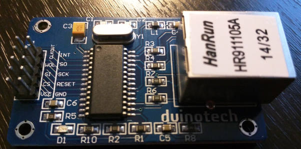
The first thing I did was look up the datasheet for the ENC28J60 Ethernet controller. I was looking for detailed information on what each of the Ten interface pins on the board did and was happy to find that almost all the information I needed was available in the document provided.
Some of the key features the controller offers that I’m interested in are:
-
Fully Compatible with 10/100/1000Base-T Networks- The interface can provide full gigabit speeds. -
Supports Full and Half-Duplex modes- Bi-directional simultaneous communication can occur on the same port, though I don’t think the Arduino won’t be-able to utilize this due to its single core/one operation at a time limitation. -
SPI Interface with Clock Speeds up to 20 MHz- SPI (Serial Peripheral Interface) will be the main way I communicate with the module. I already know there’s a very extensive SPI library available that I can learn with. -
8-Kbyte Transmit/Receive Packet Dual Port SRAM- Allows for latching (in SRAM // Static random-access memory) and queuing of packets and data when up to 8-Kbytes. Again, I don’t think this will be relevant to me but it’s still nice to know about. -
Supports Unicast, Multicast and Broadcast Packets- Self explanatory and expected on most interfaces these days. -
WOL or Magic Packet- Wake on LAN, another neat feature I’d love to explore on the board.
Pin Description
Below is the schematic provided for the ENC28J60 Ethernet controller. There are only a couple pins that we have direct access to via the Pin headers, I’ll try to explain as best I can what each of these pins are and what they do.
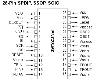
CLKOUT- The Programmable clock output pin is provided for use as the host controller clock or as a clock source for other devices in the system.- Has an internal
Prescalerwhich can divide the output by 1, 2, 3, 4 or 8. APrescaleris used to reduce a high frequency electrical signal to a lower frequency by integer division.
- Has an internal
-
INT- Interrupt output pin signals the occurrence of an interrupt event to the host controller. -
WOL- Wake on Lan pin which can be used to push a magic packet through to the Ethernet interface connected. There’s some interesting examples of this here. -
SO- Also defined asMISO (Master In Slave Out)and is used as the Slave line for sending data to the master. The master in this case is normally the Arduino or microcontroller. -
SI- Also defined asMOSI (Master Out Slave In)and is used as the Master line for sending data to the peripherals. -
SCK- The Serial clock which synchronizes the data transmission generated by the master. -
CS- Chip select the input pin for the SPI interface. It is held low while any operation is performed and returned high when finished. -
RESET- Active low device that resets the input. -
VCC- 3.3V supply input. GND- Grounding pin.
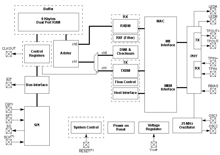
If you’re interested in the full block diagram for the controller, it can be seen below. Take note of the various pin labels we just discussed and use them to work out how the system all comes together.
Serial Peripheral Interface (SPI)
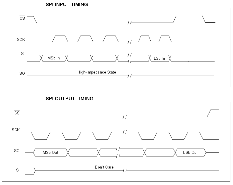
Commands and data are sent to the device via the SI pin, with data being clocked in on the rising edge of SCK. Data is driven out on the SO line on the falling edge of SCK. The CS pin must be held low while any operation is performed and returned high when finished.
Below is a timeline displaying the Pin states for both input and output.
These interfaces are mapped to the following ports on the Arduino Uno. You can find the correct pins for other boards under Connections here. Note that the ENC28J60 controller uses a different pin for CS than the normal pin 10 (SS).
-
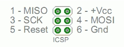
SIPin -> DigitalPin 11ORICSP-4 -
SOPin -> DigitalPin 12ORICSP-1 -
SCKPin -> DigitalPin 13ORICSP-3 -
CSPin -> DigitalPin 8
NOTE You can also use the Reset, Ground and 3.3V pins on the ICSP interface. Else just use the normal pins. You can safely ignore the RESET pin for most examples.
Ethercard Libraries + Examples
In order to get our device communicating we’ll need to use a library called Ethercard. It can be downloaded from here:
https://github.com/jcw/ethercardOnce you’ve downloaded the zip, place the contents in your Arduino libraries folder. The contents of the ethercard folder comes with a couple examples that we’ll be using to first confirm that our interfacing is correct.
Go ahead and open up the testDHCP sketch under examples and upload the code to your Arduino. Connect a networked Ethernet cable to your Ethernet module and fire up the serial monitor. You will also need to set the baud rate to 57600 (as specified in the code).
If all went well you should receive the following serial output indicating that you’ve successfully been assigned a DHCP address (your IP values will vary obviously).
[testDHCP]
MAC: 74:69:69:2D:30:31
Setting up DHCP
MyIP: 192.168.188.53
Netmask: 255.255.255.0
GW IP: 192.168.188.254
DNS IP: 192.168.188.254
Yay! We got it working. That’s a really simple example though, and we still don’t really know how it’s working. Next we’ll take a look at the code and try to build our own code from scratch.
Build a Webserver
Lets open a new project and begin. Start by adding the appropriate code to include the EtherCard library:
#include <EtherCard.h>Next we’ll setup a place where we can specify static IP information. We’ll do that by creating and populating the following byte arrays with relevant IP network information
// Ethernet interface ip address
static byte myip[] = { 192,168,188,200 };
// Gateway ip address
static byte gwip[] = { 192,168,188,254 };
// DNS ip address
static byte dnsip[] = { 192,168,188,254 };
// Subnet mask
static byte mask[] = { 255,255,255,0 };
Add a another byte array to store the mac address of the interface. You can either make up one yourself or obtain the interfaces actual address from the board itself. If you can’t be bothered with either of these things feel free to use mine.
// Ethernet mac address - must be unique on your network
static byte mymac[] = { 0x74,0x69,0x69,0x2D,0x30,0x31 };
I would also recommend adding the following line to specify the TCP/IP buffer size. We will be using this later during the interface initialization.
// TCP/IP send and receive buffer
byte Ethernet::buffer[500];
Now lets get started on the setup() code. We’ll start by opening up a serial connection for debugging with the baud rate of 57600
void setup() {
  // Open a serial connection for debugging
  Serial.begin(57600);
  Serial.println("\n[Debugger]");
Now we need to initialize the Ethernet interface using the ether.begin() function. If we have a look at the functions definition in the EtherCard.h file we can see what values it accepts.
    /**   @brief  Initialize the network interface
    *     @param  size Size of data buffer
    *     @param  macaddr Hardware address to assign to the network interface (6 bytes)
    *     @param  csPin Arduino pin number connected to chip select. Default = 8
    *     @return <i>uint8_t</i> Firmware version or zero on failure.
    */
    static uint8_t begin (const uint16_t size, const uint8_t* macaddr,
                          uint8_t csPin =8);
We can use the information above to construct the ether.begin() function using the Ethernet buffer size and our Ethernet mac address. We also want to wrap this initialization in an if statement to confirm the interface is constructed correctly. Use the following syntax to get that done:
// Initialize the Ethernet interface
if (ether.begin(sizeof Ethernet::buffer, mymac) == 0)
  Serial.println( "Failed to access Ethernet controller");
Next we need to setup the interface with either DHCP or the static values we declared earlier on. You can choose to do either by implementing one of the following solutions:
DHCP implementation
ether.dhcpSetup()Static implementation is defined in EtherCard.h
/**   @brief  Configure network interface with static IP
*     @param  my_ip IP address (4 bytes). 0 for no change.
*     @param  gw_ip Gateway address (4 bytes). 0 for no change. Default = 0
*     @param  dns_ip DNS address (4 bytes). 0 for no change. Default = 0
*     @param  mask Subnet mask (4 bytes). 0 for no change. Default = 0
*     @return <i>bool</i> Returns true on success - actually always true
*/
static bool staticSetup (const uint8_t* my_ip,
                         const uint8_t* gw_ip = 0,
                         const uint8_t* dns_ip = 0,
                         const uint8_t* mask = 0);
And therefore can be implemented as follows:
// Setup IP statically
ether.staticSetup(myip, gwip, dnsip, mask);
At this point, we should have our interface setup. Just to make sure lets write out the IP values to serial:
// Print IP information out to serial line
ether.printIp("IP:  ", ether.myip);
ether.printIp("GW:  ", ether.gwip);
ether.printIp("DNS: ", ether.dnsip);
Now that we have the interface up and running we can work on publishing a HTML page to the interface when someone tries to connect to the web server. We’ll be storing our test html page within the Arduino code itself. If you have an SD card and an SD adapter on your Arduino you can also tell the microcontroller to serve the page from the SD directory. In my case however I am simply going to build the HTML directly onto the Arduino chip.
Back at the top of your program add the following as a constant char array. It will store your text in the Arduino program memory (PROGMEM)
// Define the HTML that will be served
const char page[] PROGMEM =
"HTTP/1.0 503 Service Unavailable\r\n"
"Content-Type: text/html\r\n"
"Retry-After: 600\r\n"
"\r\n"
"<html>"
  "<head><title>"
    "Arduino Webserver Example"
  "</title></head>"
  "<body>"
    "<h3>Congratulations, you can see this page!</h3>"
    "<p><em>"
      "Keep learning!<br />"
      "And have a happy new year"
    "</em></p>"
  "</body>"
"</html>"
;
The only thing left to do is to setup some code in the loop() to serve the page whenever someone connects. This is done via the following code block:
void loop(){
  // wait for an incoming TCP packet, but ignore its contents
  if (ether.packetLoop(ether.packetReceive())) {
    memcpy_P(ether.tcpOffset(), page, sizeof page);
    ether.httpServerReply(sizeof page - 1);
  }
}
Lets explore what each of the functions in the loop() block do:
packetLoop()- Waits for and accepts a TCP/IP connection from the Ethernet interface. In this case thepacketReceive()function is the parameter this function takes.
static uint16_t packetLoop (uint16_t plen);

/**   @brief  Accept a TCP/IP connection
*     @param  port IP port to accept on - do nothing if wrong port
*     @param  plen Number of bytes in packet
*     @return <i>uint16_t</i> Offset within packet of TCP payload. Zero for no data.
*/packetReceive()- Defined in theenc28j60.hfile, this function copies the packet data from the Ethernet controllers memory and passes it to thepacketLoop()function
static uint16_t packetReceive ();

/**   @brief  Copy data from ENC28J60 memory
*     @param  page Data page of memory
*     @param  data Pointer to buffer to copy data to
*/memcpy_P- Takes three arguments:destination- ether.tcpOffset() will receive our bytessource- The declared page array we declared and stored in PROGMEMnum- The number of bytes we want to copy to destination, in this case it’s thesizeof(returns size in bytes) thepage array
tcpOffset()- Initializes the SPI interface and serves as a input for the TCP payload
static uint8_t* tcpOffset () { return buffer + 0x36; } //!< Pointer to the start of TCP payload

/**   @brief  Initialise SPI interface
*     @note   Configures Arduino pins as input / output, etc.
*/httpServerReply()- advises the interface of how many bytes make up the TCP payload. In this case it’s the byte size of the page array minus 1
static void httpServerReply (uint16_t dlen);

/**   @brief  Send a response to a HTTP request
*     @param  dlen Size of the HTTP (TCP) payload
*     @param  flags TCP flags
*/
And that is it!, if you run your code and navigate to the IP address either set statically or assigned to you via DHCP in a web browser, you should be greeted with the HTML page you defined in the page array.
Congratulations, you can see this page!

Keep learning!
And have a happy new year
Conclusion
That was fun! Difficult, but very fun once I’d found the datasheet for the Ethernet controller. Something I’ve noticed is that I’ve become a lot better at tracking down information myself instead of relying on other peoples description to explain things to me. I think it’s important to do things like what I did in this post; instead of relying on something else’s knowledge to solve a problem, try to understand why everything happens rather than simply accepting that it does.
Below is a full copy of the code I used during the implementation. Also be sure to check the github link and have a browse of the libraries that come with EtherCard.
#include <EtherCard.h>

// Ethernet interface ip address
static byte myip[] = { 192,168,188,200 };
// Gateway ip address
static byte gwip[] = { 192,168,188,254 };
// DNS ip address
static byte dnsip[] = { 192,168,188,254 };
// Subnet mask
static byte mask[] = { 255,255,255,0 };

// Ethernet mac address - must be unique on your network
static byte mymac[] = { 0x74,0x69,0x69,0x2D,0x30,0x31 };

// TCP/IP send and receive buffer
byte Ethernet::buffer[500];

// Define the HTML that will be served
const char page[] PROGMEM =
"HTTP/1.0 503 Service Unavailable\r\n"
"Content-Type: text/html\r\n"
"Retry-After: 600\r\n"
"\r\n"
"<html>"
  "<head><title>"
    "Arduino Webserver Example"
  "</title></head>"
  "<body>"
    "<h3>Congratulations, you can see this page!</h3>"
    "<p><em>"
      "Keep learning!<br />"
      "And have a happy new year"
    "</em></p>"
  "</body>"
"</html>"
;

void setup() {
  // Open a serial connection for debugging
  Serial.begin(57600);
  Serial.println("\n[Debugger]");

  // Initialize the Ethernet interface
  if (ether.begin(sizeof Ethernet::buffer, mymac) == 0)
    Serial.println( "Failed to access Ethernet controller");

  // Setup IP statically
  ether.staticSetup(myip, gwip, dnsip, mask);

  // Print IP information out to serial line
  ether.printIp("IP:  ", ether.myip);
  ether.printIp("GW:  ", ether.gwip);
  ether.printIp("DNS: ", ether.dnsip);
}

void loop(){
  // wait for an incoming TCP packet, but ignore its contents
  if (ether.packetLoop(ether.packetReceive())) {
    memcpy_P(ether.tcpOffset(), page, sizeof page);
    ether.httpServerReply(sizeof page - 1);
  }
}