Introduction
I’ve had to use an LCD display a couple times with some projects in the past, but never really understood what I was doing as I followed tutorials telling me what to plug where. Today I decided I would go through and document what each pin does on a standard 16x2 LCD display does and try to get it printing my Blogs title.
The Pins
There are 16 pins on a standard 2x16 LCD Display
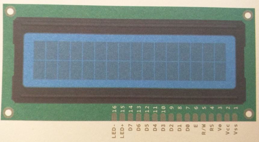
- Vss
- This is the
Negative supply; or theground pin. It is excepted to be at 0V, so in almost every case you will just link this pin straight to your circuitsGND pin.
- This is the
- Vcc
Positive supply voltage. This is the pin we use to power the main LCD module. There is a separate pin for the actual backlight (see pin 15-16).
- Vø
- This is how we adjust the contrast of our display. Generally a
potentiometeror any other device that will allow for variable settings
- This is how we adjust the contrast of our display. Generally a
- RS
Register selectorallows us to toggle between the command and data registersCommand Registeris selected with the RS Pin is Low. It tells the LCD that a command is being send to the display. Examples of commands could be Clear Display, Home Cursor, Entry Mode Set etc…Data Registeris the opposite and is selected with the RS Pin is High. It tells the LCD that the incoming stream is data that needs to be displayed.- You will find that there is already a library that will do all the RS pin toggling for you, but it’s still good to understand the difference between the two. If you’d like to know more about some of the commands, there is a great tutorial on LCDs Here.
- R/W
Low to writeto the register;High to readfrom the register. There are some situations where you might want to read from the LCD display back into the program. It isn’t something that you will need to deal with often, but it’s another interesting thing to understand.
- E
Enabling pin; when this pin is set tological low, the LCD does not care what is happening withR/W,RS, and thedata bus lines; when this pin is set tological high, the LCD is processing the incoming data. It allows us to check if the LCD is still processing data that it has been given, so that we don’t write onto lines and corrupt our output.
- D0
- 8-bit data pin 0
- D1
- 8-bit data pin 1
- D2
- 8-bit data pin 2
- D3
- 8-bit data pin 3
- D4
- 8-bit data pin 4
- D5
- 8-bit data pin 5
- D6
- 8-bit data pin 6
- D7
- 8-bit data pin 7
- LED+
Backlight Vcc positive supply. This pin powers the LCD backlight and normally runs at5V
- LED-
Backlight GND negative supply. This pin is theGNDpin for the backlight. Expected to be0V
Wire up the LCD
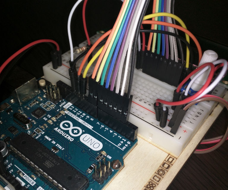
Next I wired up the LCD using the following configurations.
LCD Pin 1 -> GND
LCD Pin 2 -> 5V
LCD Pin 3 -> Input from potentiometer
LCD Pin 4 -> Digital Pin 12
LCD Pin 5 -> Digital Pin 13
LCD Pin 6 -> Digital Pin 11
LCD Pin 7 -> Digital Pin 2
LCD Pin 8 -> Digital Pin 3
LCD Pin 9 -> Digital Pin 4
LCD Pin 10 -> Digital Pin 5
LCD Pin 11 -> Digital Pin 6
LCD Pin 12 -> Digital Pin 7
LCD Pin 13 -> Digital Pin 8
LCD Pin 14 -> Digital Pin 9
LCD Pin 15 -> 220Ω Resistor in series with 5V input
LCD Pin 16 -> GND
Below is an example of how I wired it up. Yours might look completely different; especially with this many wires, it isn’t easy to keep things neat.
Writing the Code
To start with we’re going to want to define our pin constants as we’ll be referencing them a lot. Make sure you use logical naming conventions.
// Map Register selector
const int lcd_RS = 12;

// Map Read/Write register
const int lcd_RW = 13;

// Map Enabling pin
const int lcd_E = 11;

// Map LCD Data Pins
const int lcd_D0 = 2; // Data 0
const int lcd_D1 = 3; // Data 1
const int lcd_D2 = 4; // Data 2
const int lcd_D3 = 5; // Data 3
const int lcd_D4 = 6; // Data 4
const int lcd_D5 = 7; // Data 5
const int lcd_D6 = 8; // Data 6
const int lcd_D7 = 9; // Data 7
The next bit is tricky, we need to find a way to take all the various mapped pins and write out to them. Luckily there’s already libraries in place that we can use. For this example we’re just using the standard LiquidCrystal library; which can be imported into our project by adding the following to the top of the file.
#include <LiquidCrystal.h>In order to access the functions within the LiquidCrystal library we just imported, we first need to create an LCD object that we can use to interact with various functions. I referred to the following while trying to track down what the default constructors for the LiquidCrystal object were and found that I had four options.
LiquidCrystal(rs, enable, d4, d5, d6, d7)
LiquidCrystal(rs, rw, enable, d4, d5, d6, d7)
LiquidCrystal(rs, enable, d0, d1, d2, d3, d4, d5, d6, d7)
LiquidCrystal(rs, rw, enable, d0, d1, d2, d3, d4, d5, d6, d7)
What it meant was that I’d done more work then I needed to, as the LCD display can function with just four data pins, the select pin and enable. All those wires for nothing!

Since there’s no harm including all the inputs, I went ahead and used the constructor that required all inputs to be defined. The following code was added, ensuring I was referencing the constants I defined earlier on.
LiquidCrystal lcd(lcd_RS, lcd_RW, lcd_E,
  lcd_D0, lcd_D1, lcd_D2, lcd_D3, lcd_D4, lcd_D5, lcd_D6, lcd_D7);
Now that I had an LCD object created, I could start accessing the Functions that are available as part of the LiquidCrystal class
Documentation on the various Functions can be found here, but the important ones I needed to start with were:
-
begin() - Initializes the interface to the LCD screen, and specifies the dimensions (width and height) of the display. begin() needs to be called before any other LCD library commands.
-
print() - Prints text to the LCD.
I added the following lines of code in order to Initialize the LCD and write out Hello, World to the screen. The parameters lcd.begin() takes are lcd.begin(cols, rows).
lcd.begin(16,2);
lcd.print("Hello, World!");
Compiled the code and loaded it onto the board….
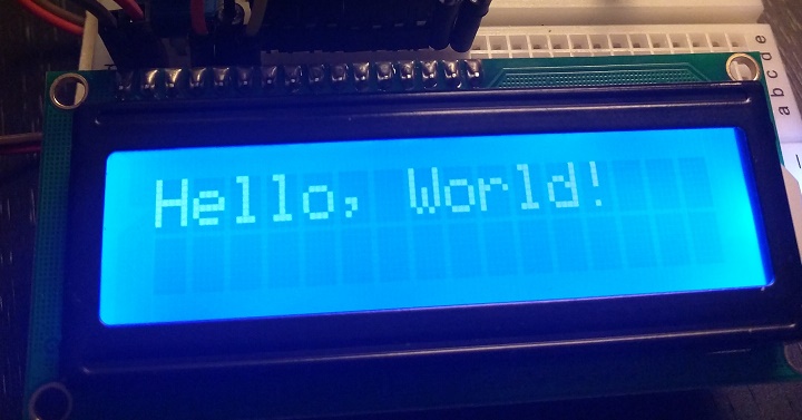
Sweet, that worked great! Lets try getting it to print out my blogs title
lcd.begin(16,2);
lcd.print("TwoFactor Assimilation");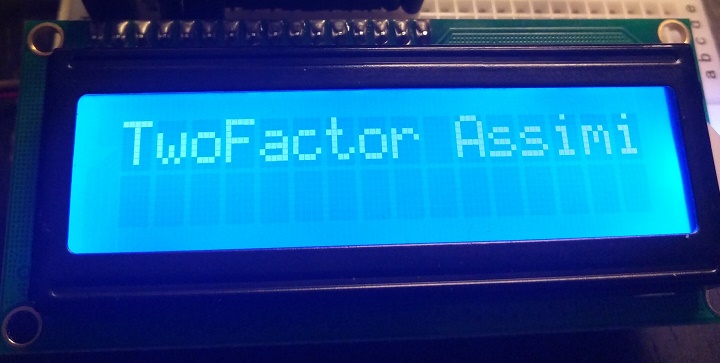
Oh dear… That didn’t work how I’d hoped. The issue occurs because the LCD only has a particular number of slots it can write into per row. Because my blog title is longer than 16 characters we lose the portion of text that overflows.
This is where another function will come in handy
setCursor() - Position the LCD cursor; that is, set the location at which subsequent text written to the LCD will be displayed.
This means that using the parameters lcd.setCursor(col, row) I can tell the board to move the position I’m writing in from down to the second row before printing Assimilation.
lcd.begin(16,2);
lcd.print("TwoFactor");
lcd.setCursor(0,2);
lcd.print("Assimilation");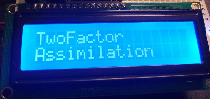
And look at that, I can now read the entire name with no issues!
Conclusion
There’s a tonne of things you can do with the LiquidCrystal libraries, so don’t yet this be all you do. Something interesting you could look into is having text centered (by moving the cursor around), or even having scrolling text.
In the future I would like to use LCDs a lot more and spent a fair amount of time tonight reading up on the functions behind the pretty libraries.
If you’d like to learn more, check out This page I mentioned before. Either that or even this page which goes into more depth of how the LCD works on an assembler level.