Contents
- Initialize Devices
- 1.1. Initialize and reload routers
- Configure Device Basic Settings
- 2.1. Configure PCs
- 2.2. Configure R1
- 2.3. Configure R2
- 2.4. Configure R3
- 2.5. Save device configurations to Flash
- Configure PPP Connections
- 3.1. Configure R1
- 3.2. Configure R2
- 3.3. Configure R3
- 3.4. Verify network connectivity
- Configure NAT
- 4.1. Configure R2
- 4.2. Verify network connectivity
- 4.3. Verify NAT Configuration on R2
- Monitor the Network
- 5.1. Configure NTP
- 5.2. Configure Syslog messaging
- 5.3. Configure SNMP on R1
- 5.4. Collect NetFlow data on R2
- 5.5. Verify monitoring configurations
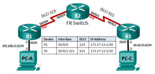
- Configure Frame Relay
- 6.1. Reload routers and restore the BasicConfig to memory
- 6.2. Configure R2 as a Frame Relay Switch
- 6.3. Configure R1
- 6.4. Configure R3
- 6.5. Verify network connectivity
- 6.6. Verify Frame Relay configuration
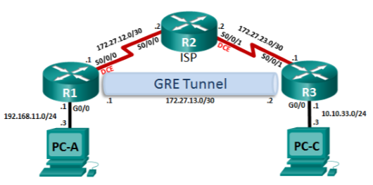
- Configure a GRE VPN Tunnel
- 7.1. Reload routers and restore the BasicConfig to memory
- 7.2. Configure Serial Interfaces
- 7.3. Configure the GRE VPN tunnel and EIGRP on R1
- 7.4. Configure the GRE VPN tunnel and EIGRP on R3
- 7.5. Verify network connectivity
- 7.6. Verify GRE VPN configuration
NOTE: This guide is based on the following: https://www.youtube.com/watch?v=0vyxmBJ1lxc
Topology
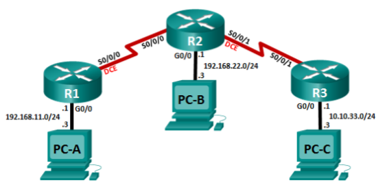
1. Initialize Devices
Initialize and reload routers
Erase the startup-config file on all routers.
R1>enable
R1#erase startup-config

Erasing the nvram filesystem will remove all configuration files! Continue? [confirm]
[OK]

Erase of nvram: complete
%SYS-7-NV_BLOCK_INIT: Initialized the geometry of nvram
Reload all routers.
R1#reload

Proceed with reload? [confirm]
2. Configure Device Basic Settings
Configure PCs
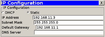
Configure static IPv4 address information on PC-A.
Configure static IPv4 address information on PC-B.

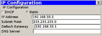
Configure static IPv4 address information on PC-C.
Configure R1
Disable DNS lookup
Router(config)#no ip domain-lookupRouter name
Router(config)#hostname R1Encrypted privileged EXEC password
R1(config)#enable secret classConsole access password
R1(config)#line console 0
R1(config-line)#password cisco
R1(config-line)#login
Telnet access password
R1(config)#line vty 0 15
R1(config-line)#password cisco
R1(config-line)#login
Encrypt the plain text passwords
R1(config)#service password-encryptionMOTD banner
R1(config)#banner motd &Unauthorized Access is Prohibited!&Configure G0/0
R1(config)#int g0/0
R1(config-if)#description Connection to 192.168.11.0 LAN
R1(config-if)#ip address 192.168.11.1 255.255.255.0
R1(config-if)#no shutdown

%LINK-5-CHANGED: Interface GigabitEthernet0/0, changed state to up
Configure R2
Disable DNS lookup
Router(config)#no ip domain-lookupRouter name
Router(config)#hostname R2Encrypted privileged EXEC password
R2(config)#enable secret classConsole access password
R2(config)#line console 0
R2(config-line)#password cisco
R2(config-line)#login
Telnet access password
R2(config)#line vty 0 15
R2(config-line)#password cisco
R2(config-line)#login
Encrypt the plain text passwords
R2(config)#service password-encryptionMOTD banner
R2(config)#banner motd &Unauthorized Access is Prohibited!&Configure G0/0
R2(config)#int g0/0
R2(config-if)#description Connection to 192.168.22.0 LAN
R2(config-if)#ip address 192.168.22.1 255.255.255.0
R2(config-if)#no shutdown

%LINK-5-CHANGED: Interface GigabitEthernet0/0, changed state to up
Configure R3
Disable DNS lookup
Router(config)#no ip domain-lookupRouter name
Router(config)#hostname R3Encrypted privileged EXEC password
R3(config)#enable secret classConsole access password
R3(config)#line console 0
R3(config-line)#password cisco
R3(config-line)#login
Telnet access password
R3(config)#line vty 0 15
R3(config-line)#password cisco
R3(config-line)#login
Encrypt the plain text passwords
R3(config)#service password-encryptionMOTD banner
R3(config)#banner motd &Unauthorized Access is Prohibited!&Configure G0/0
R3(config)#int g0/0
R3(config-if)#description Connection to 192.168.33.0 LAN
R3(config-if)#ip address 192.168.33.1 255.255.255.0
R3(config-if)#no shutdown

%LINK-5-CHANGED: Interface GigabitEthernet0/0, changed state to up
Save device configurations to Flash
Copy the running-config on R1 to flash. Name the file BasicConfig
R1#copy running-config BasicConfig
R1#copy running-config startup-config
Copy the running-config on R2 to flash. Name the file BasicConfig
R2#copy running-config BasicConfig
R2#copy running-config startup-config
Copy the running-config on R3 to flash. Name the file BasicConfig
R3#copy running-config BasicConfig
R3#copy running-config startup-config
3. Configure PPP Connections
Configure R1
Configure S0/0/0
R1(config)#int s0/0/0
R1(config-if)#description PPP Connection to R2
R1(config-if)#ip address 172.27.12.1 255.255.255.252
R1(config-if)#clock rate 128000
R1(config-if)#no shutdown

%LINK-5-CHANGED: Interface Serial0/0/0, changed state to down
Configure CHAP authentication on S0/0/0
R1(config-if)#encapsulation ppp
R1(config-if)#ppp authentication chap
Create a local database entry for CHAP authentication
R1(config)#username R2 password ciscoSet a static default route out S0/0/0
R1(config)#ip route 0.0.0.0 0.0.0.0 s0/0/0

%Default route without gateway, if not a point-to-point interface, may impact performance
Configure R2
Configure S0/0/0
R2(config)#int s0/0/0
R2(config-if)#description PPP Connection to R1
R2(config-if)#ip address 172.27.12.2 255.255.255.252
R2(config-if)#no shutdown
Configure CHAP authentication on S0/0/0
R2(config-if)#encapsulation ppp
R2(config-if)#ppp authentication chap
Create a local database entry for CHAP authentication
R2(config-if)#username R1 password ciscoConfigure S0/0/1
R2(config)#int s0/0/1
R2(config-if)#description PPP Connection to ISP
R2(config-if)#ip address 209.165.200.225 255.255.255.248
R2(config-if)#clock rate 128000
R2(config-if)#encapsulation ppp
R2(config-if)#no shutdown
Set a static default route out S0/0/1
R2(config)#ip route 0.0.0.0 0.0.0.0 s0/0/1

%Default route without gateway, if not a point-to-point interface, may impact performance
Set a static route for R1 LAN traffic out S0/0/0
R2(config)#ip route 192.168.11.0 255.255.255.0 s0/0/0

%Default route without gateway, if not a point-to-point interface, may impact performance
Configure R3
Configure S0/0/1
R3(config)#int s0/0/1
R3(config-if)#description PPP Connection R2
R3(config-if)#ip address 209.165.200.230 255.255.255.248
R3(config-if)#encapsulation ppp
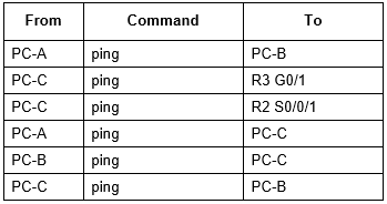
R3(config-if)#no shutdownVerify network connectivity
4. Configure NAT
Configure R2
Assign a static NAT to map the inside local IP address for PC-B to a Inside Global address
R2(config)#ip nat inside source static 192.168.22.3 209.165.200.226Define an access control list to permit the R1 LAN for dynamic NAT
R2(config)#access-list 1 permit 192.168.11.0 0.0.0.255Define the dynamic NAT pool for the R1 LAN
R2(config)#ip nat pool R1-LAN 209.165.200.227 209.165.200.227 netmask 255.255.255.248Define the NAT from the inside source to the outside pool. Make sure to allow multiple PCs access to this single Inside Global address
R2(config)#ip nat inside source list 1 pool R1-LAN overloadDefine an access control list to permit the R2 LAN for dynamic NAT
R2(config)#access-list 2 permit 192.168.22.0 0.0.0.255Define the dynamic NAT pool for the R2 LAN
R2(config)#ip nat pool R2-LAN 209.165.200.228 209.165.200.228 netmask 255.255.255.248Define the NAT from the inside source to the outside pool. Make sure to allow multiple PCs access to this single Inside Global address
R2(config)#ip nat inside source list 2 pool R2-LAN overloadAssign the outside NAT interface
R2(config)#int s0/0/1
R2(config-f)#ip nat outside
Assign the inside NAT interface for the R1 LAN
R2(config)#int s0/0/0
R2(config-f)#ip nat inside
Assign the inside NAT interface for the R2 LAN
R2(config)#int g0/0
R2(config-f)#ip nat inside
Verify network connectivity

Verify NAT Configuration on R2
Display configured access lists
R2#show access-listsDisplay the current active NAT translations
R2#show ip nat translationsDisplay detailed information about NAT including interface, access list, and pool assignments
R2#show ip nat statistics5. Monitor the Network
Configure NTP
Set the clock on R2 to a date and time specified for NTP testing
R2#clock set 9:00:00 25 August 2013Configure R2 as the NTP Master
R2(config)#ntp master 5Configure R1 so that it uses R2 as its NTP Server
R1(config)#ntp server 172.27.12.2Configure Syslog messaging
Enable the timestamp service on R1 and R2 for system logging purposes
R1(config)#service timestamp log datetime msec
R2(config)#service timestamp log datetime msec
Enable logging of messages on R1 and R2
R1(config)#logging host 192.168.11.3
R2(config)#logging host 192.168.11.3
Change message trapping level on R1 and R2
R1(config)#logging trap debugging
R2(config)#logging trap debugging
Configure SNMP on R1
Create a standard access list to permit the SNMP management station (PC-A) to retrieve SNMP information from R1
R1(config)#ip access-list standard SNMP-ACCESS
R1(config-std-nacl)#permit 192.168.11.3
Enable SNMP community access to the SNMP-ACCESS access list
R1(config)#snmp-server community SA-LAB ro SNMP-ACCESSSet the SNMP notification host
R1(config)#snmp-server host 192.168.11.3 version 2c SA-LABEnable all SNMP traps
R1(config)#snmp-server enable trapsCollect NetFlow data on R2
Configure NetFlow data capture on both serial interfaces. Capture ingress and egress data packets
R2(config)#int s0/0/0
R2(config-if)#ip flow ingress
R2(config-if)#ip flow egress
R2(config)#int s0/0/1
R2(config-if)#ip flow ingress
R2(config-if)#ip flow egress
Configure NetFlow data export
R2(config)#ip flow-export destination 192.168.22.3 9996Configure the NetFlow export version
R2(config)#ip flow-export version 9Verify monitoring configurations
Display the date and time
R2#show clockDisplay the contents of logging buffers
R2#show loggingDisplay information about the SNMP communities
R2#show snmp communityDisplay the protocol using the highest volume of traffic
R2#show ip cache flow6. Configure Frame Relay
Reload routers and restore the BasicConfig to memory
Erase the startup configurations and reload the devices
R1#show flash
R1#reload
R2#show flash
R2#reload
R3#show flash
R3#reload
For each router, issue the copy flash:BasicConfig running-config command to reload the basic configuration that you saved at the end of Part 2
R1#copy flash:BasicConfig running-config
R2#copy flash:BasicConfig running-config
R3#copy flash:BasicConfig running-config
Issue the no shutdown command for the G0/0 interface on R1 and R3
R1(config)#int g0/0
R1(config-if)#no shutdown
R3(config)#int g0/0
R3(config-if)#no shutdown
Configure R2 as a Frame Relay Switch
R2(config)#frame-relay switching
R2(config)#int s0/0/0
R2(config-if)#encapsulation frame-relay
R2(config-if)#frame-relay intf-type dce
R2(config-if)#frame-relay route 123 interface s0/0/1 321
R2(config-if)#frame-relay lmi-type ansi
R2(config-if)#no shutdown
R2(config-if)#int s0/0/1
R2(config-if)#clock rate 128000
R2(config-if)#encapsulation frame-relay ietf
R2(config-if)#frame-relay intf-type dce
R2(config-if)#frame-relay route 321 interface s0/0/0 123
R2(config-if)#no shutdown
Configure R1
Configure S0/0/0
R1(config)#int s0/0/0
R1(config-if)#description Frame Relay Connection to R3
R1(config-if)#ip address 172.27.13.1 255.255.255.252
R1(config-if)#encapsulation frame-relay
R1(config-if)#clock rate 128000
R1(config-if)#no shutdown
Disable Inverse ARP on S0/0/0
R1(config)#int s0/0/0
R1(config-if)#no frame-relay inverse-arp
Map the IP local address to the DLCI
R1(config-if)#frame-relay map ip 172.27.13.1 123Map the remote IP address to the DLCI. Allow for multicast or broadcast traffic
R1(config-if)#frame-relay map ip 172.27.13.2 123 broadcastChange the LMI type to the ANSI standard
R1(config-if)#frame-relay lmi-type ansiActivate the interface
R1(config-if)#no shutdownCreate a default route to the IP address on the other side of the Frame Relay link
R1(config)#ip route 0.0.0.0 0.0.0.0 172.27.13.2Configure R3
Configure S0/0/1
R3(config)#int s0/0/1
R3(config-if)#encapsulation frame-relay ietf
R3(config-if)#no shutdown
Create a point-to-point subinterface on S0/0/1
R3(config)#int s0/0/1.321 point-to-point
R3(config-subif)#description Frame Relay Connection to R1
Set the Layer 3 IPv4 address on the subinterface
R3(config-subif)#ip address 172.27.13.2 255.255.255.252Disable Inverse ARP on the subinterface
R3(config-subif)#no frame-relay inverse-arpMap the subinterface to the DLCI
R3(config-subif)#frame-relay interface-dlci 321Create a default route to the IP address on the other side of the Frame Relay link
R3(config)#ip route 0.0.0.0 0.0.0.0 172.27.13.1Verify network connectivity
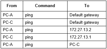
Verify Frame Relay configuration
Display Frame Relay LMI statistics
R1#show frame-relay lmiDisplay the input and output packet count totals on a Frame Relay permanent virtual circuit (PVC)
R1#show frame-relay pvcDisplay the Frame Relay maps between DLCIs and IP addresses
R1#show frame-relay map7. Configure a GRE VPN Tunnel
Reload routers and restore the BasicConfig to memory
Erase the startup configurations and reload the devices
R1#show flash
R1#reload
R2#show flash
R2#reload
R3#show flash
R3#reload
For each router, issue the copy flash:BasicConfig running-config command to reload the basic configuration that you saved at the end of Part 2
R1#copy flash:BasicConfig running-config
R2#copy flash:BasicConfig running-config
R3#copy flash:BasicConfig running-config
Issue the no shutdown command for the G0/0 interface on R1 and R3
R1(config)#int g0/0
R1(config-if)#no shutdown
R3(config)#int g0/0
R3(config-if)#no shutdown
Configure Serial Interfaces
R1 Configure S0/0/0
R1(config)#int s0/0/0
R1(config-if)#description HDLC Connection to ISP
R1(config-if)#ip address 172.27.12.1 255.255.255.252
R1(config-if)#encapsulation hdlc
R1(config-if)#clock rate 128000
R1(config-if)#no shutdown
R2 Configure S0/0/0
R2(config)#int s0/0/0
R2(config-if)#description HDLC Connection to R1
R2(config-if)#ip address 172.27.12.2 255.255.255.252
R2(config-if)#encapsulation hdlc
R2(config-if)#no shutdown
R2 Configure S0/0/1
R2(config)#int s0/0/1
R2(config-if)#description HDLC Connection to R3
R2(config-if)#ip address 172.27.23.2 255.255.255.252
R2(config-if)#encapsulation hdlc
R2(config-if)#clock rate 128000
R2(config-if)#no shutdown
R3 Configure S0/0/1
R3(config)#int s0/0/1
R3(config-if)#description HDLC Connection to ISP
R3(config-if)#ip address 172.27.23.1 255.255.255.252
R3(config-if)#encapsulation hdlc
R3(config-if)#no shutdown
Configure the GRE VPN tunnel and EIGRP on R1
Create a GRE tunnel interface
R1(config)#int tunnel 0
R1(config-if)#description GRE VPN tunnel to R3
R1(config-if)#ip address 172.27.13.1 255.255.255.252
Use S0/0/0 as the tunnel source
R1(config-if)#tunnel source s0/0/0Set the tunnel destination with the IP address of the R3 S0/0/1 interface
R1(config-if)#tunnel destination 172.27.23.1Create a default route out S0/0/0
R1(config)#ip route 0.0.0.0 0.0.0.0 s0/0/0Configure EIGRP on R1
R1(config)#router eigrp 1Advertise the LAN and Tunnel subnets in EIGRP. Set the LAN interface to passive
R1(config-router)#network 192.168.11.0 0.0.0.255
R1(config-router)#network 172.27.13.0 0.0.0.3
R1(config-router)#passive-interface g0/0
Configure the GRE VPN tunnel and EIGRP on R3
Create a GRE tunnel interface
R3(config)#int tunnel 0
R3(config-if)#description GRE VPN Tunnel to R1
R3(config-if)#ip address 172.27.13.2 255.255.255.252
Use S0/0/1 as the tunnel source
R3(config-if)#tunnel source s0/0/1Set the tunnel destination with the IP address of the R1 S0/0/0 interface
R3(config-if)#tunnel destination 172.27.12.1Create a default route out S0/0/1
R3(config)#ip route 0.0.0.0 0.0.0.0 s0/0/1Configure EIGRP on R3
R3(config)#router eigrp 1Advertise the LAN and Tunnel subnets in EIGRP. Set the LAN interface to passive.
R3(config-router)#network 10.10.33.0 0.0.0.255
R3(config-router)#network 172.27.13.0 0.0.0.3
R3(config-router)#passive-interface g0/0
Verify network connectivity
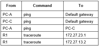
Verify GRE VPN configuration
Display detail information about the GRE tunnel interface
R1#show interface tunnel 0