Contents
-
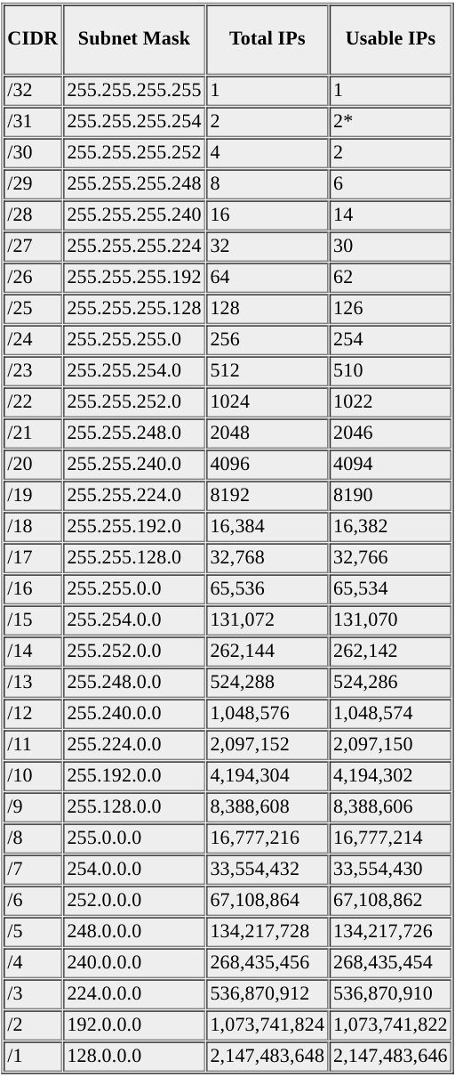
Subnetting Reference
- Common Setup
- Hostname
- Privileged Exec Password
- Secure main Access Lines
- Message of the Day
- Password Length Policy
- Password Encryption
- Password Limit Login Attempts
- Disable Domain Lookup
- Save Configuration
- Clear Configuration
- SSH Configure
- Configure Domain
- Set Hostname on Device
- Generate RSA Key (1024)
- Set SSH Version 2
- Configure vty line to accept SSH
- Configure user-based Authentication
- Configure Interface
- Assign IP Address
- Description
- Speed
- Duplex
- Shutdown/Start up
- DCE Clock Rate
- Serial Bandwidth
- Configure Static Route
- Setup Default route to internet
- Static Route to neighbor network
- OSPF Configuration
- Enable OSPF with Process ID 1
- OSPF Router ID
- OSPF Link Cost
- OSPF Network assignment
- Prevent Routing updates being sent to LAN
- OSPF MD5 Authentication
- EIGRP Configuration
- Display the directly connected networks
- Configure EIGRP to advertise to directly connected networks
- Configure Passive Interface (Prevent Updates sent to LAN)
- Disable Auto Summary
- Verify EIGRP Routing
- Manual Summary Calculations
- Manual Summary Address - Example 1
- Manual Summary Address - Example 2
- Manual Summary of the Previous Examples
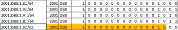
- IPv6 Manual Summary - Example 1
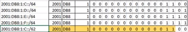
- IPv6 Manual Summary - Example 2
- IPv6 Manual Summary of the Previous Examples
- VLANs and Trunking
- Creating VLANs
- Assign Switch Ports to VLANs
- Switchport Static Access
- Sub-interface configuration
- Defines the encapsulation format as IEEE 802.1Q (dot1q)
- Specifies the VLAN identifier
- EtherChannel and Trunking
- Channel 1 and 2 initiate negotiations
- Channel 3 side B should negotiate with side C
- Channel 3 side C should not initiate negotiations with B
- Configure Static Trunking on switchport
- Switch Security
- Configure port security on all active access ports
- Accept only two MAC addresses
- MAC addresses should be recorded
- Switchport should provide notification, but not place interface in disabled state.
- Configure DHCP
- DHCP Pool Creation
- Exclude the first five addresses from pool.
- Configure Access Control Lists
- Create a named standard ACL using the name MANAGE
- Allow only the host on 203.0.113.18 access
- Apply this policy to the VTY lines
- Create an Access list with number 101
- Allow external host 203.0.113.18 full access to inside network
- Allow outside access to 198.51.100.14 over HTTP only
- Allow responses to data requests to enter the Network
- Activate access list on interface
- Spanning Tree Protocol
- Activate Rapid PVST+ and set root priorities
- FL-A should be configured as root primary for VLAN 2 and VLAN 4 using the default primary priority values.
- FL-A should be configured as root secondary for VLAN 8 and VLAN 15 using the default secondary priority values.
- FL-C should be configured as root primary for VLAN 8 and VLAN 15 using the default primary priority values.
- FL-C should be configured as root secondary for VLAN 2 and VLAN 4 using the default secondary priority values.
- Activate PortFast and BPDU Guard on the active FL-C switch access ports.
- On FL-C, configure PortFast on the access ports that are connected to hosts.
- On FL-C, activate BPDU Guard on the access ports that are connected to hosts.
- NAT
- Translate the internal address of the server to the address 198.51.100.14
- Configure the correct interfaces to perform this NAT translation
- Configure Dynamic NAT, Use a pool name of INTERNET
- Hosts on LAN can use Internet, source list number 1
0. Subnetting Reference
I’ll make this more beautiful when I have more time
1. Common Setup
Configure Hostname
Router(config)#hostname R1Privileged Exec Password
R1(config)#enable secret class12345Secure main Access Lines
R1(config)#line console 0
R1(config-line)#password cisco12345
R1(config-line)#login
R1(config-line)#logging synchronous
R1(config-line)#exec-timeout 60
R1(config-line)#exit

R1(config)#line vty 0 4
R1(config-line)#password cisco12345
R1(config-line)#transport input ssh
R1(config-line)#login local
R1(config-line)#logging synchronous
R1(config-line)#exec-timeout 60
R1(config-line)#exit

R1(config)#line aux 0
R1(config-line)#password cisco12345
R1(config-line)#login
R1(config-line)#logging synchronous
R1(config-line)#exec-timeout 60
Message of the Day
R1(config)#banner motd @Please only enter if you are cool!@Password Length Policy
R1(config)#security passwords min-length 10Password Encryption
R1(config)#service password-encryptionPassword Limit Login Attempts
R1(config)#login block-for 120 attempts 2 within 30Disable Domain Lookup
R1(config)#no ip domain-lookup2. SSH Configure
Configure Domain
R1(config)#ip domain-name cisco.uaSet Hostname on Device
R1(config)#hostname R1Generate RSA Key (1024)
R1(config)#crypto key generate rsa
!1024
Set SSH Version 2
R1(config)#ip ssh version 2Configure vty line to accept SSH
R1(config)#line vty 0 4
R1(config-line)#login local
R1(config-line)#transport input ssh
R1(config)#line vty 5 15
R1(config-line)#login local
R1(config-line)#transport input ssh
Configure user-based Authentication
User: netadmin
Pass: SSH_secret9
R1(config)#username netadmin password SSH_secret9
Save Configuration
R1#copy running-config startup-configClear Configuration
Routers:
R1# clear config all
This command will clear all configuration in NVRAM.
This command will cause ifIndex to be reassigned on the next system startup.
Do you want to continue (y/n) [n]? y

Switches:
S1# write erase
Erasing the nvram filesystem will remove all files! Continue? [confirm]y[OK]
Erase of nvram: complete
S1#
S1# reload
3. Configure Interface
Assign IP Address
R1>enable
R1#configure terminal
R1(config)#interface FastEthernet0/0
R1(config-if)#ip address 192.168.1.1 255.255.255.0
Description
R1(config)#interface FastEthernet0/0
R1(config-if)#description Private LAN
Speed
R1(config)#interface FastEthernet0/0
R1(config-if)#speed 100
Duplex
R1(config)#interface FastEthernet0/0
R1(config-if)#duplex full
Shutdown/Start up
R1(config)#interface FastEthernet0/0
R1(config-if)#no shutdown

R1(config)#interface FastEthernet0/0
R1(config-if)#shutdown
DCE Clock Rate
R1(config)#int s0/0/0
R1(config-if)#clock rate 128000
Serial Bandwidth
R1(config)#int s0/0/0
R1(config-if)#bandwidth 128
4. Configure Static Route
Setup Default route to internet
R1(config)#ip route 0.0.0.0 0.0.0.0 s0/0/0
R2(config)#ip route 0.0.0.0 0.0.0.0 s0/1/0
R3(config)#ip route 0.0.0.0 0.0.0.0 s0/0/1
Static Route to neighbour network
R1(config)#ip route 192.168.200.0 255.255.252.0 s0/0/0
R2(config)#ip route 192.168.200.0 255.255.252.0 s0/0/1
5. OSPF Configuration
Enable OSPF with Process ID 1
Bldg-1(config)#router ospf 1OSPF Router ID
Bldg-1(config)#router ospf 1
Bldg-1(config-router)#router-id 1.1.1.1
OSPF Link Cost
Bldg-1(config)#int s0/0/0
Bldg-1(config-if)#ip ospf cost 7500
OSPF Network assignment
Bldg-1(config)#router ospf 1
Bldg-1(config-router)#network 192.168.100.20 0.0.0.3 area 0
Bldg-1(config-router)#network 192.168.8.0 0.0.0.255 area 1
Bldg-1(config-router)#network 192.168.9.0 0.0.0.255 area 1

Main(config)#router ospf 1
Main(config-router)#network 192.168.100.20 0.0.0.3 area 0
Main(config-router)#network 192.168.100.36 0.0.0.3 area 0

Bldg-2(config)#router ospf 1
Bldg-2(config-router)#network 192.168.100.36 0.0.0.3 area 0
Bldg-2(config-router)#network 10.10.2.0 0.0.0.255 area 2
Bldg-2(config-router)#network 10.10.4.0 0.0.0.255 area 2
Bldg-2(config-router)#network 10.10.8.0 0.0.0.255 area 2
Bldg-2(config-router)#network 10.10.15.0 0.0.0.255 area 2
Prevent Routing updates being sent to LAN
Bldg-1(config)#router ospf 1
Bldg-1(config-router)#passive-interface GigabitEthernet0/0
Bldg-1(config-router)#passive-interface GigabitEthernet0/1

Main(config)#router ospf 1
Main(config-router)#passive-interface Serial0/1/0

Bldg-2(config)#router ospf 1
Bldg-2(config-router)#passive-interface GigabitEthernet0/1
Bldg-2(config-router)#passive-interface g0/1.2
Bldg-2(config-router)#passive-interface g0/1.4
Bldg-2(config-router)#passive-interface g0/1.8
Bldg-2(config-router)#passive-interface g0/1.15
OSPF MD5 Authentication
- Use a key value of 1
- Use xyz_OSPF as the password
- Apply MD5 authentication to the required interfaces

Bldg-1(config)#int s0/0/0
Bldg-1(config-if)#ip ospf message-digest-key 1 md5 xyz_OSPF
Bldg-1(config-if)#ip ospf authentication message-digest

Main(config)#int s0/1/0
Main(config-if)#ip ospf message-digest-key 1 md5 xyz_OSPF
Main(config-if)#ip ospf authentication message-digest
6. EIGRP Configuration
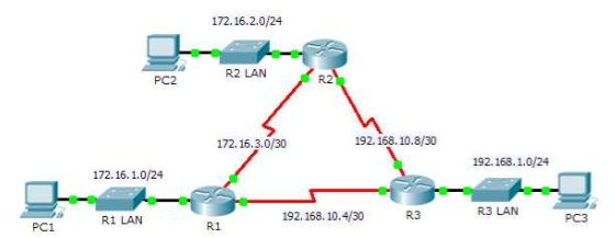
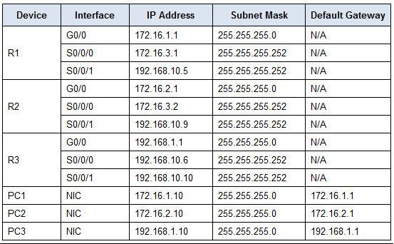
Display the directly connected networks
R1(config-router)#do show ip route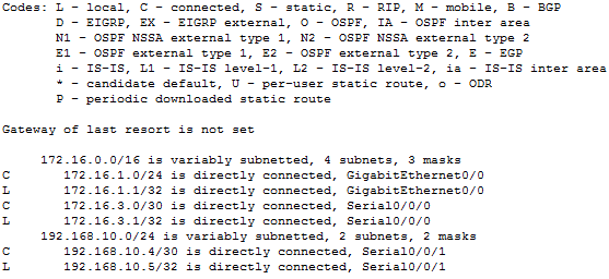
Configure EIGRP to advertise to directly connected networks
R1(config-router)#network 172.16.1.0 0.0.0.255
R1(config-router)#network 172.16.3.0 0.0.0.3
R1(config-router)#network 192.168.10.4 0.0.0.3

R2(config-router)#network 172.16.2.0 0.0.0.255
R2(config-router)#network 172.16.3.0 0.0.0.3
R2(config-router)#network 192.168.10.8 0.0.0.3

R3(config-router)#network 192.168.1.0 0.0.0.255
R3(config-router)#network 192.168.10.4 0.0.0.3
R3(config-router)#network 192.168.10.8 0.0.0.3
Configure Passive Interface (Prevent Updates sent to LAN)
R1(config-router)#passive-interface g0/0
R2(config-router)#passive-interface g0/0
R3(config-router)#passive-interface g0/0
Disable Auto Summary
R1(config)#router eigrp 1
R1(config-router)#no auto-summary
Verify EIGRP Routing
R1#show ip eigrp neighbors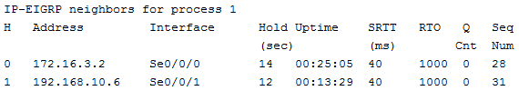
Manual Summary Calculations
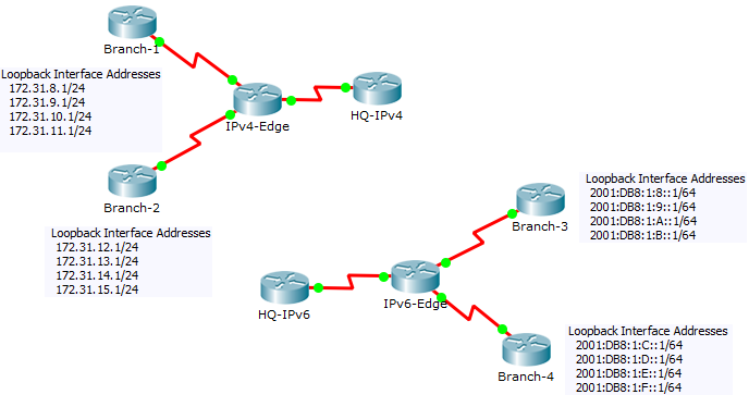
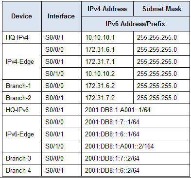
Manual Summary Address - Example 1
- Find the Last place a common bit pattern occurs in the 4 octets. This will be our summary
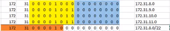
Branch-1(config)#int s0/0/0
Branch-1(config-if)#ip summary-address eigrp 1 172.31.8.0 255.255.252.0
Manual Summary Address - Example 2
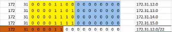
Branch-2(config-if)#int s0/0/1
Branch-2(config-if)#ip summary-address eigrp 1 172.31.12.0 255.255.252.0
Manual Summary of the Previous Examples
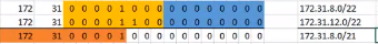
IPv4-Edge(config)#int s0/1/0
IPv4-Edge(config-if)#ip summary-address eigrp 1 172.31.8.0 255.255.248.0
IPv6 Manual Summary - Example 1
Branch-3(config)#ipv6 router eigrp 1
Branch-3(config-rtr)#eigrp router-id 3.3.3.3
Branch-3(config-rtr)#int s0/0/0
Branch-3(config-if)#ipv6 summary-address eigrp 1 2001:DB8:1:8::/62
IPv6 Manual Summary - Example 2
Branch-4(config)#ipv6 router eigrp 1
Branch-4(config-rtr)#eigrp router-id 4.4.4.4
Branch-4(config-rtr)#int s0/0/1
Branch-4(config-if)#ipv6 summary-address eigrp 1 2001:DB8:1:C::/62
IPv6 Manual Summary of the Previous Examples
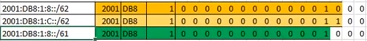
HQ-IPv6(config)#ipv6 router eigrp 1
HQ-IPv6(config-rtr)#eigrp router-id 1.1.1.1
HQ-IPv6(config)#int s0/0/1
HQ-IPv6(config-if)#ipv6 summary-address eigrp 1 2001:DB8:1:8::/61
7. VLANs and Trunking
Creating VLANs
FL-A(config)#vlan 2
FL-A(config-vlan)#name dept1
FL-A(config)#vlan 4
FL-A(config-vlan)#name dept2
FL-A(config)#vlan 8
FL-A(config-vlan)#name dept3
FL-A(config)#vlan 15
FL-A(config-vlan)#name NetAdmin
FL-A(config)#vlan 25
FL-A(config-vlan)#name manage
FL-A(config)#vlan 99
FL-A(config-vlan)#name safe
Assign Switch Ports to VLANs
FL-A(config)#interface fa0/5
FL-A(config-if)#switchport access vlan 2
FL-A(config-if)#no shutdown

FL-A(config)#interface fa0/10
FL-A(config-if)#switchport access vlan 4
FL-A(config-if)#no shutdown

FL-A(config-if)#switchport access vlan 8
FL-A(config-if)#no shutdown

FL-A(config)#interface fa0/24
FL-A(config-if)#switchport access vlan 15
FL-A(config-if)#no shutdown
Switchport Static Access
FL-A(config)#interface fa0/5
FL-A(config-if)#switchport mode access

FL-A(config)#interface fa0/10
FL-A(config-if)#switchport mode access

FL-A(config)#interface fa0/15
FL-A(config-if)#switchport mode access

FL-A(config)#interface fa0/24
FL-A(config-if)#switchport mode access
Sub-interface configuration Defines the encapsulation format as IEEE 802.1Q (dot1q), and specifies the VLAN identifier Specifies the VLAN identifier
PoliceDept(config)#int g0/0
PoliceDept(config-if)#no shutdown
PoliceDept(config-if)#int g0/0.45
PoliceDept(config-subif)#encapsulation dot1Q 45
PoliceDept(config-subif)#ip address 192.168.45.1 255.255.255.0
PoliceDept(config-subif)#int g0/0.47
PoliceDept(config-subif)#encapsulation dot1Q 47
PoliceDept(config-subif)#ip address 192.168.47.1 255.255.255.0
PoliceDept(config-subif)#int g0/0.101
PoliceDept(config-subif)#encapsulation dot1Q 101
PoliceDept(config-subif)#ip address 192.168.101.1 255.255.255.0
8. EtherChannel and Trunking
Channel 1 and 2 initiate negotiations
FL-A(config)#interface range fa0/1-2
FL-A(config-if-range)#channel-group 1 mode active
FL-A(config-if-range)#no shutdown

FL-A(config)#interface range fa0/3-4
FL-A(config-if-range)#channel-group 2 mode active
FL-A(config-if-range)#no shutdown

FL-A(config)#interface port-channel 1
FL-A(config-if)#switchport mode trunk

FL-A(config)#interface port-channel 2
FL-A(config-if)#switchport mode trunk

FL-B(config)#interface range fa0/3-4
FL-B(config-if-range)#channel-group 2 mode active
FL-B(config-if-range)#no shutdown

FL-B(config)#interface port-channel 2
FL-B(config-if)#switchport mode trunk

FL-C(config)#interface range fa0/1-2
FL-C(config-if-range)#channel-group 1 mode active
FL-C(config-if-range)#no shutdown

FL-C(config)#interface port-channel 1
FL-C(config-if)#switchport mode trunk
Channel 3 side B should negotiiate with side C
FL-B(config)#interface range fa0/5-6
FL-B(config-if-range)#channel-group 3 mode active
FL-B(config-if-range)#no shutdown

FL-B(config)#interface port-channel 3
FL-B(config-if)#switchport mode trunk
Channel 3 side C should not initiate negotiations with B
FL-C(config)#interface range fa0/5-6
FL-C(config-if-range)#channel-group 3 mode passive
FL-B(config-if-range)#no shutdown

FL-C(config)#interface port-channel 3
FL-C(config-if)#switchport mode trunk
Configure Static Trunking on switchport
FL-B(config)#interface g0/1
FL-B(config-if)#switchport mode trunk
9. Switch Security
Configure port security on all active access ports
FL-A(config)#interface fa0/5
FL-A(config-if)#switchport port-security

FL-A(config)#interface fa0/10
FL-A(config-if)#switchport port-security

FL-A(config)#interface fa0/15
FL-A(config-if)#switchport port-security

FL-A(config)#interface fa0/24
FL-A(config-if)#switchport port-security
Accept only two MAC addresses
FL-A(config)#interface fa0/5
FL-A(config-if)#switchport port-security maximum 2
FL-A(config)#interface fa0/10
FL-A(config-if)#switchport port-security maximum 2
FL-A(config)#interface fa0/15
FL-A(config-if)#switchport port-security maximum 2
FL-A(config)#interface fa0/24
FL-A(config-if)#switchport port-security maximum 2
MAC addresses should be recorded
FL-A(config)#interface fa0/5
FL-A(config-if)#switchport port-security mac-address sticky
FL-A(config)#interface fa0/10
FL-A(config-if)#switchport port-security mac-address sticky
FL-A(config)#interface fa0/15
FL-A(config-if)#switchport port-security mac-address sticky
FL-A(config)#interface fa0/24
FL-A(config-if)#switchport port-security mac-address sticky
Switchports should provide notification, but not place interface in disabled state
FL-A(config)#interface fa0/5
FL-A(config-if)#switchport port-security violation restrict
FL-A(config)#interface fa0/10
FL-A(config-if)#switchport port-security violation restrict
FL-A(config)#interface fa0/15
FL-A(config-if)#switchport port-security violation restrict
FL-A(config)#interface fa0/24
FL-A(config-if)#switchport port-security violation restrict
10. Configure DHCP
DHCP Pool Creation
Bldg-2(config)#ip dhcp pool vlan2pool
Bldg-2(dhcp-config)#network 10.10.2.0 255.255.255.0
Bldg-2(dhcp-config)#default-router 10.10.2.1
Bldg-2(dhcp-config)#dns-server 192.168.200.225
Exclude the first five addresses from pool
Bldg-2(config)#ip dhcp excluded-address 10.10.2.1 10.10.2.5
Bldg-2(config)#ip dhcp excluded-address 10.10.4.1 10.10.4.5
Bldg-2(config)#ip dhcp excluded-address 10.10.8.1 10.10.8.5
11. Configure Access Control Lists
Create a named standard ACL using the name MANAGE
Central(config)#ip access-list standard MANAGEAllow only the host on 203.0.113.18 access
Central(config-std-nacl)#permit host 203.0.113.18Apply this policy to the VTY lines
Central(config)#line vty 0 4
Central(config-line)#password class
Central(config-line)#login
Central(config-line)#access-class MANAGE in
Create an Access list with number 101 Allow external host 203.0.113.18 full access to inside network
Central(config)#access-list 101 permit ip host 203.0.113.18 anyAllow outside access to 198.51.100.14 over HTTP only
Central(config)#access-list 101 permit tcp any host 198.51.100.14 eq wwwAllow responses to data requests to enter the Network
Central(config)#access-list 101 permit tcp any any established
Central(config)#access-list 101 deny ip any any
Activate access list on interface
Central(config)#int s0/1/0
Central(config-if)#ip access-group 101 in
12. Spanning Tree Protocol
Activate Rapid PVST+ and set root priorities
FL-A(config)#spanning-tree mode rapid-pvst
FL-B(config)#spanning-tree mode rapid-pvst
FL-C(config)#spanning-tree mode rapid-pvst
FL-A should be configured as root primary for VLAN 2 and VLAN 4 using the default primary priority values
FL-A(config)#spanning-tree vlan 2 root primary
FL-A(config)#spanning-tree vlan 4 root primary
FL-A should be configured as root secondary for VLAN 8 and VLAN 15 using the default secondary priority values
FL-A(config)#spanning-tree vlan 8 root secondary
FL-A(config)#spanning-tree vlan 15 root secondary
FL-C should be configured as root primary for VLAN 8 and VLAN 15 using the default primary priority values
FL-C(config)#spanning-tree vlan 8 root primary
FL-C(config)#spanning-tree vlan 15 root primary
FL-C should be configured as root secondary for VLAN 2 and VLAN 4 using the default secondary priority values
FL-C(config)#spanning-tree vlan 2 root secondary
FL-C(config)#spanning-tree vlan 4 root secondary
Activate PortFast and BPDU Guard on the active FL-C switch access ports On FL-C, configure PortFast on the access ports that are connected to hosts
FL-C(config)#interface range fa0/7, fa0/10, fa0/15, fa0/24
FL-C(config-if-range)#spanning-tree portfast
On FL-C, activate BPDU Guard on the access ports that are connected to hosts
FL-C(config)#interface range fa0/7, fa0/10, fa0/15, fa0/24
FL-C(config-if-range)#spanning-tree bpduguard enable
FL-C(config-if-range)#no shutdown
13. NAT
Translate the internal address of the server to the address 198.51.100.14
Central(config)#ip nat inside source static 192.168.18.46 198.51.100.14Configure the correct interfaces to perform this NAT translation
Central(config)#int g0/0
Central(config-if)#ip nat inside
Central(config-if)#int s0/1/0
Central(config-if)#ip nat outside
Configure Dynamic NAT, Use a pool name of INTERNET
Central(config)#ip nat pool INTERNET 198.51.100.3 198.51.100.13 netmask 255.255.255.240Hosts on LAN can use Internet, source list number 1
Central(config)#access-list 1 permit 192.168.45.0 0.0.0.255
Central(config)#access-list 1 permit 192.168.47.0 0.0.0.255
Central(config)#access-list 1 permit 192.168.200.0 0.0.3.255
Central(config)#ip nat inside source list 1 pool INTERNET